|
|
Post by dave1800 on Sept 28, 2017 9:56:18 GMT
Hi Nick
Impressive use of 3D printing in such a short time should encourage others to have a go. The chain angle at the bottom left still looks a bit too tight - can you lower the gear at all to reduce it? Is it possible to get any idea at this stage of the potential for the cam advance /retard range?
regards
David
|
|
|
|
Post by 1800heap on Sept 28, 2017 10:19:39 GMT
Hi David
I am currently running a 5 hour print that should allow a 12 tooth gear to fit which is about the best I'm going to get without going longer with the chain.
What also causes a problem is the further out one cog is the bigger or further out the other cog has to be to compensate. You have to move an even amount of chain either side, so the tension remains similar throughout the range of movement. The V9 range was roughly 12 degrees.
Nick
|
|
|
|
Post by dave1800 on Oct 2, 2017 5:49:03 GMT
Hi Nick
A stupid question, have you considered rollers to try and smooth out the angles and maybe incorporate the tensioner in the roller arrangement?
regards
David
|
|
|
|
Post by 1800heap on Oct 9, 2017 9:03:58 GMT
Hi Nick A stupid question, have you considered rollers to try and smooth out the angles and maybe incorporate the tensioner in the roller arrangement? regards David Hi David Sorry for the slow reply. Actually an interesting question which I did consider. I had a look for rubberised rollers to do just that. The problem I found was the limited selection of sizes available. I really needed to be able to have fairly specific inner and outer diameter on each side. The bigest problem with this setup is keeping the chain at a reasonably even tension as the angles change. A big disadvantage with using sprockets is sizes are naturally limited anyway because you can't have 11.5 teeth say! However I found a company that will make sprockets to order. This seemed like a more feasible option for a prototype, rather than having a rubberised roller made. I suspect though if the system does infact work ok and I get that far, a rubberised roller may well be better to reduce noise and angles. At least on the tensioner side. Talking about the tensioning, I am reluctant to get rid of the standard unit as it also oils the chain as you know. I was hoping to show another couple of pictures but I am struggling a bit with the location of the tensioner and having time to play with it! I was hoping to move it but retain the original bolt holes in the block. This is not possible though. The previous picture shows a modified and moved tensioner but I realised this mod is a mistake. I think I must retain the original shape tensioner and place it at the same angle to the chain as it was on the standard setup, otherwise it won't tension correctly. This means a mod to the block and front plate unfortunately. I have for the most part done the CAD work for the new front plate. Getting all the holes in the proper positions has been a nightmare! Bit of a learning curve! Im not a draftsman! I now have to work out the new location. Crab VVT certainly looks a more possible propersition now than when I first decided to look at it. So not a stupid question at all. In fact the most obvious things don't necessarily stand out with this kind of project, so the more silly questions the merrier as far as Im concerned! Nick |
|
|
|
Post by dave1800 on Oct 17, 2017 0:41:00 GMT
Another week another stupid question! Why do you need two gears, wouldn't it be possible to retain the tensioner in its original position but modify it so the ratchet did not prevent the plunger from returning. It may require a stronger spring, I'm unclear as to the proportion of tension attributed to the spring vs oil pressure.
There must be a good reason, I'm missing the obvious.
regards
David
|
|
|
|
Post by 1800heap on Oct 18, 2017 2:31:07 GMT
Hi David
So far I have only considered using two sprockets! Thats a curly one. Im not sure you could get away with one. I don't think it would be possible while keeping the original tensioner anyway.
The main problem when using the original tensioner is the limited range of movement. It would not be able to take up all the slack as a single sprocket moves round to change the timing. It might if redesigned though.
Correct me if I am wrong but the little ratchet device inside the tensioner foot stops it from being pushed back in too far when there is no oil pressure at startup. More of a problem with an old slack chain I suspect. Im not sure why go for oil pressure for tensioning instead of just a spring. It may be because of lubricating the chain. Reliability perhaps? More force (up to a point) with more engine speed? You have to replace it with some other system though. Especially as this set up requires some way to transfer slack in the chain as the timing moves, which I have done with the second sprocket. You could probably change the proportion of tension provided by the spring v oil. Currently majority via oil pressure I think although not tested.
The other problem is keeping a sufficient section of chain wrapped arround the crank sprocket and not taking up lots of space.
Food for thought anyway
Nick
|
|
|
|
Post by dave1800 on Oct 20, 2017 4:35:59 GMT
Hi Nick
If you redesigned the head of the tensioner so that it was longer (ie in contact with more of the chain) wouldn't that give you greater effective range but it would require greater pressure I assume.
The ratchet prevents the plunger from being forced back by the chain tension but maybe increasing the strength of the internal spring could compensate for this, possibly not too difficult to try while turning the engine by hand? The roller type of tensioners I have seen don't appear to have any ratchet mechanism although they do have hefty springs.
Just throwing out ideas!
regards
David
|
|
|
|
Post by 1800heap on Oct 22, 2017 6:53:49 GMT
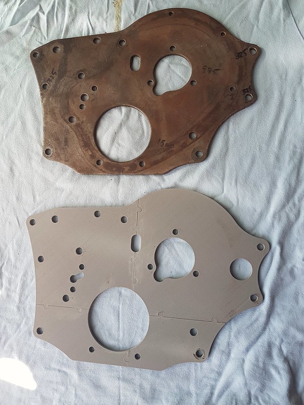
Hi David If you happen to come across a picture of the roller tensioner you are talking about please post it. I am not considering any changes to the plan at this stage. But may do if I can't get the current tensioner idea to work! Here is a picture of the the progress of the front plate.  The 3D print is in 4 parts and is super glued together because the printer bed is too small to do it in one! It is an accurate reproduction so that I can mess about with the tensioner location a bit further. If you compare the two I have moved the tensioner holes. I wanted to use the original tensioner as I said and this plate has the holes in it for that. Unfortunately the location on this print is a compromise because in the perfect spot the bolt holes are too close to the original location holes! I need more clearance sadly so this plate has proved to me using the original tensioner in the compromise spot won't work! I have now realised I can get it where I want by using the oil hole as a bolt hole and re-drilling a new oil hole! Strange but true! I am now back round in a big circle and I will have to make a new tensioner case but where I thought I was out of options, I now have one I think that will work. I wan't to be able to modify the block but not in a way that stops me from reverting to standard gear! I also only have one chance at modifying the block so want to be damn sure its right the first time! One step closer anyway! I have to replace a fan on the 3D printer. Mind you its has done many hours of printing already. The front plate takes about 18 hours for all 4 parts! Nick |
|
|
|
Post by 1800heap on Oct 25, 2017 9:02:30 GMT
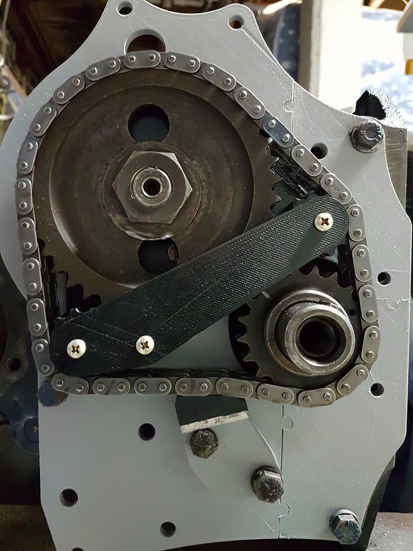
Well I think I may have an ok tensioner location finally although it all still needs some minor adjustment. I need a little more slack on the chain as it is all a bit tight. The tensioner is set at the same angle to the chain as the original was, so I am much happier that it will work properly. 
The foot of the tensioner is standard, the body needed a redesign to be able to use one of the standard bolt holes to make it fit. It still needs a tidy up but the basic design seem ok. The angles are as good as they are going to get with this design and I think should work ok. So as you can see an new back plate will be required also a new tensioner body retaining the standard foot. Then the VVT unit itself. I still have to set up the actuator and design the adapter for that. I have the motor and driver to start that thanks to ebay, so that is next on the things to do list. Pointless doing any more unless I can sort that side out! Then electronics I suppose, which I may have to lean on David a bit for help with!  Give it a couple of years who knows!! Nick |
|
|
|
Post by dave1800 on Oct 26, 2017 0:38:04 GMT
Hi Nick It's looking good now that you have managed to sort out the angles. I'll do some research to see what is required for the elecronics. I have worked out in principle at least how the ignition program we already have can be modified as the cam advance is changed. Not sure if that can compensate sufficiently for any differences in the fuelling requirements. I wonder if Andew A has details from his rolling road tune ups that may provide a few pieces of the jig saw? I guess a rolling road may be essential to determine what is required. regards David Then electronics I suppose, which I may have to lean on David a bit for help with!  Give it a couple of years who knows!! Nick |
|