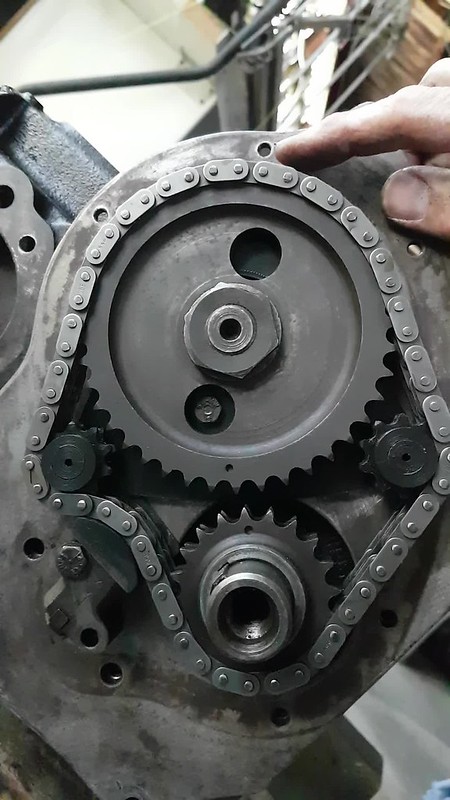
|
|
Post by hydrolastic on Apr 16, 2017 3:08:36 GMT
VVt is entirely possible but not in the way you think. I would like to try putting a fourvalve twincam head on a b series engine. I have done a couple of the BMW twincam A series and the results are so amazing its tempting to give it a go. I looked at a 90 mm Bore spacing B18 head but its a CCW engine so a toyota or nissan 90 to 92 mm BC head would be cool. I have heard that somebody already has done one but i cant find anything on it. Aaron
|
|
|
|
Post by dave1800 on Apr 16, 2017 8:51:13 GMT
Sort of like this? Mini If you are in a hurry skip to around 14 minutes in. David |
|
|
|
Post by 1800heap on Apr 16, 2017 12:05:47 GMT
Now that sounds like a plan Aaron. Twin cam giddy up! I probably don't have the technology to do it sadly, unless it was a bolt on job.
I have an mgb crossflow head sitting in a box waiting for me to use one day, but I want to fuel inject it and don't have the money for that yet! I have read mixed reviews about them since I got it 5 or six years ago unfortunately!
As I said before a single cam engine is not very ideal and not going to break any records as a VVT. Best I can hope for is to spread the power out a bit!
Nick
|
|
|
|
Post by 1800heap on Apr 16, 2017 12:06:52 GMT
Nice Mini David shame its not yours!
Nick
|
|
|
|
Post by hydrolastic on Apr 20, 2017 0:17:26 GMT
 This is the latest one. 115 hp at 6500rpm out of 1360cc. 80 hp at 4000. 100 hp at 5000. Minispares 5 speed. Megasquirt FI. Counterweighted crank. This one also gets a idle air control valve. Will idle like a kitten. Stay cool and will out accelerate all but the most extreme race engines. |
|
|
|
Post by 1800heap on Apr 20, 2017 6:24:58 GMT
Well Aaron that looks like a gofundme project.
Crab twin cam! Love to see a b series crab engine done. I shall await your picture of it to match the tasty looking mini engine.
Nick
|
|
|
|
Post by 1800heap on Aug 13, 2017 9:32:06 GMT
Hi all
A quick update on the VVT project.
I have managed to prove the principal. I still have several issues to solve including getting oil to the various parts required. I have 3D printed a couple of cogs and parts and made a mock up. The clearances are very tight but it might just work. I think I can get at least 12 degrees adjustment on the cam sprocket. Unfortunately I will have to redesign the front plate and obviously the timing chain cover to suit the new setup. Not at this stage though! I am trying to keep the tensioner with a mod to the slipper head. I am not certain if this is possible until I have fiddled with the geometry a bit. It is all a very tight fit!
Those of you who have done some work with hotter cams I need a little direction. I am very green with the setup of the timing of these cams and need a little help with this side. I have only done the standard timing setup. Ie two dots lined up on a standard cam! I am wondering how I would work out where to set the best center point to give a useful range of adjustment, to get the best results out of a cam. I suppose this will vary with the cam?
Also can anyone tell me how the vernier cam sprocket compairs clearance wise to a standard sprocket. I am interested in the rear clearance, as part of the mechanism will tuck in behind a standard cam sprocket just!
Regard
Nick
|
|
|
|
Post by dave1800 on Aug 16, 2017 1:21:32 GMT
Hi Nick Some thoughts to get the ball rolling. I find it useful to go back to basics when trying to tackle a new and challenging project. I think that the Moss Motor short videos on camshafts are an ideal starting point to refresh memories without a headache. (1-5 relate to cam profiles, 6-8 setting the timing marks) Moss 1Moss 2Moss 3Moss 4Moss 5Moss 6Moss 7Moss 8If you wish to advance and retard a camshaft then I think a useful range would be +/- 5 degrees although some MGB owners have suggested up to 8 degrees. On the stock cam retarding the cam timing 5 degrees would probably shift the whole torgue curve up by 500 rpm and advancing down the rpm range by 500 rpm. I would anticipate that hotter cams are more sensitive to changes. Here is a summary copied from the internet. I would expect some changes to the ignition timing may be needed but hopefully the fuelling would sort itself out with a bit of tweaking without the need for needle mods. The single chains and gears fitted to Mk111 cars may provide more room to mount your actuator, I'm not sure. You may be able to get away without a vernier cam adjuster if it's a problem or use offset keys which would not restrict the space but can be a pain. From the net Cam advance
Advancing the camshaft (the intake & exhaust valves both open & close earlier) has these general effects:
» cranking pressure (gauge pressure) is increased
» tendency to knock at low speed is increased
» low speed power is increased
» idle speed is increased
» peak torque is increased, but may be at lower RPM
» peak power may be reduced
» intake valve to piston clearance is reduced
» exhaust valve to piston clearance is increased
» traction (for ½ mile, &c. racing) is reduced
» overlap duration is not affected, but engine vacuum may change
» idle and low speed exhaust note is louder, due to both earlier intake closing and exhaust opening
» LSA is not affected
If power continues to go up as the cam is advanced beyond 8°, the cam is probably too large (especially: the intake closing point is too late), or the engine needs more compression.
________________________________________
Cam retard
Retarding the camshaft (the intake & exhaust valves both open & close later) has these general effects:
» cranking pressure is reduced
» tendency to knock at low speed is reduced
» low speed power is reduced
» idle speed is probably reduced
» idle smoothness is increased
» peak torque may be reduced, but at higher RPM
» peak power may be increased
» intake valve to piston clearance increased
» exhaust valve to piston clearance reduced
» traction (for ½ mile, &c. racing) is increased
» overlap duration is not affected, but engine vacuum may change
» idle and low speed exhaust note is softer, due to both later intake closing and exhaust opening
» LSA is not affected
If power continues to go up as the cam is retarded beyond 4°, the cam is probably too small (especially: the overlap is too short, or LSA too wide).
regards David Hi all A quick update on the VVT project. I have managed to prove the principal. I still have several issues to solve including getting oil to the various parts required. I have 3D printed a couple of cogs and parts and made a mock up. The clearances are very tight but it might just work. I think I can get at least 12 degrees adjustment on the cam sprocket. Unfortunately I will have to redesign the front plate and obviously the timing chain cover to suit the new setup. Not at this stage though! I am trying to keep the tensioner with a mod to the slipper head. I am not certain if this is possible until I have fiddled with the geometry a bit. It is all a very tight fit! Those of you who have done some work with hotter cams I need a little direction. I am very green with the setup of the timing of these cams and need a little help with this side. I have only done the standard timing setup. Ie two dots lined up on a standard cam! I am wondering how I would work out where to set the best center point to give a useful range of adjustment, to get the best results out of a cam. I suppose this will vary with the cam? Also can anyone tell me how the vernier cam sprocket compairs clearance wise to a standard sprocket. I am interested in the rear clearance, as part of the mechanism will tuck in behind a standard cam sprocket just! Regard Nick |
|
|
|
Post by 1800heap on Aug 17, 2017 6:57:00 GMT
Thanks for all the info David.
I usually look at posts on here with my phone but it refuses to open links on the forum for some reason. I haven't had a chance to look at the Moss stuff yet as I have to use a PC to do it!
Nick
|
|
|
|
Post by dave1800 on Aug 17, 2017 7:42:07 GMT
Hi Nick
I've just checked the links on my computer and they all open, just standard Youtube videos. Don't you just love IT until it doesn't work!
David
|
|
|
|
Post by 1800heap on Aug 19, 2017 9:34:47 GMT
Thanks for the Moss links they were very interesting. Should help when the time comes.
I am almost ready to print version 5 of the assembly which should fit much better I think. I will shim the cam cog 0.05" to improve my clearance issue, then I think it will be ok. I will have to do the same with the crank gear obviously, so I hope that doesn't cause any unseen problems. The cam locating plate is part of my assemby so adding 0.05" to that is easy. I am just trying to get my head around how to CAD draw an involute gear properly for the mechanism. It takes about 7 hours to print the idler plate so I want to do a first try of the gear section on this print! Watching plenty of utube videos about it!
Nick
|
|
|
|
Post by 1800heap on Aug 19, 2017 9:39:02 GMT
Forgot to mention I had thought of the simplex chain but I think the relatively tight bend around my idlers may stress it too much. I will go there if I really have to though.
Nick
|
|
|
|
Post by dave1800 on Aug 25, 2017 9:35:25 GMT
Hopefully a 50 thou shim shouldn't be an issue although I recall reading somewhere that there are some non original oil throwers in Australia that are the wrong shape so you would need to check it doesn't foul the timing cover. How's the CAD drawing of the involute gear going? regards David Thanks for the Moss links they were very interesting. Should help when the time comes. I am almost ready to print version 5 of the assembly which should fit much better I think. I will shim the cam cog 0.05" to improve my clearance issue, then I think it will be ok. I will have to do the same with the crank gear obviously, so I hope that doesn't cause any unseen problems. The cam locating plate is part of my assemby so adding 0.05" to that is easy. I am just trying to get my head around how to CAD draw an involute gear properly for the mechanism. It takes about 7 hours to print the idler plate so I want to do a first try of the gear section on this print! Watching plenty of utube videos about it! Nick |
|
|
|
Post by 1800heap on Aug 26, 2017 3:34:08 GMT
Hi David Thanks for the heads up about the oil thrower. I have managed to sort out the involute gear drawing I think yes. I am not happy with the pitch so I will probably change it. I have printed the new part and actually fitted it to the engine roughly. It just fits with a slightly modified tensioner. I am going to have to move the tensioner to improve the angles. There is a new problem I have noticed. One idler ends up close to the water pump so my plan for the timing cover will have to change! Anyway here is a video clip which shows the operation. Not quite there but works more or less! Click on the photo 
VVTNick |
|
|
|
Post by 1800heap on Sept 28, 2017 7:16:34 GMT
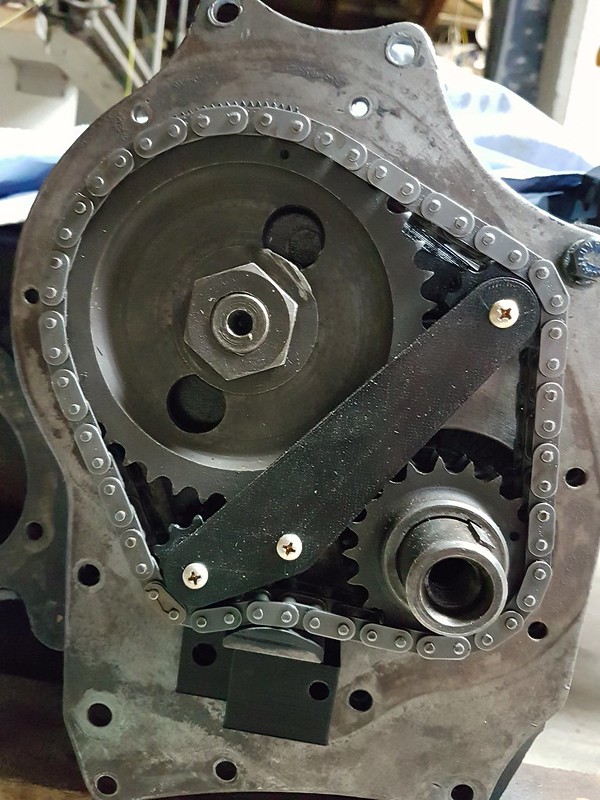
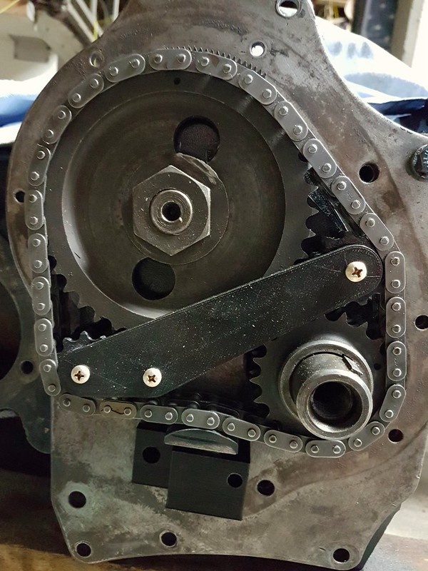
Here are another couple of pictures of the V9 VVT 3d printed setup. This time it includes the reinforcing plate to help keep it square. I am still tinkering with the angles but this one looks a bit better. Now printing version 11. I am going to try with a larger 12 tooth sprocket on the tensioner side. As you can see the tensioner has moved a bit and is now a 3D print. I have to make another foot as it is now the wrong shape! Rather than wast another real foot I will probably print them, so I can mess around with the profile until I am happy with it. If anyone has any ideas feel free to comment.   Nick |
|